

1. Click New
2. Click Option  (Tools>Option…) , select Document Properties tab. Select Units , under Unit System select IPS (inch, pound, second) OK.
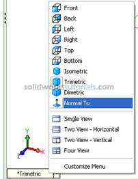
3. Select Top Plane , from lower left menu select Normal To. 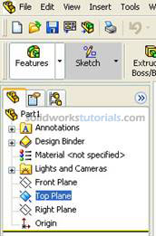
4. Click Sketch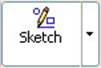 in Command Manager, click Rectangle
 . As you can see on upper right corner sketch icon appear indicate that you’re on sketch mode
 .
.
in Command Manager, click Rectangle. As you can see on upper right corner sketch icon appear indicate that you’re on sketch mode.5. Pick Origin point as starting point, drag to right hand side
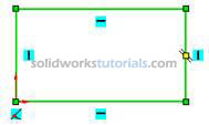 no need to be exact the size will define in later step. Press keyboard ESC to end rectangle sketch.
no need to be exact the size will define in later step. Press keyboard ESC to end rectangle sketch.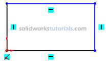
Note: There is two type line generated by your sketching, the one with black line and blue line. Black line is line that fully defined and blue line is under defined.
6. Define sketch with dimension. Click Smart Dimension , and start dimensioning pick vertical line and set to 2.00in , pick horizontal line and set to 2.00in
 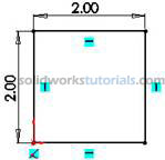 . Press keyboard ESC to end smart dimension
, and start dimensioning pick vertical line and set to 2.00in , pick horizontal line and set to 2.00in . Press keyboard ESC to end smart dimension7. Build feature from sketch, click Features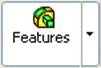 and activate features menu. Click Extruded Boss/Base
 and set D1 to 0.5in
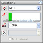 and
and  .
. 
and activate features menu. Click Extruded Boss/Base and set D1 to 0.5in and 8. Click front top face 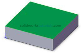 , click Normal To
 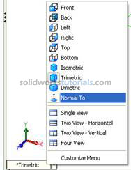 . Activate sketch menu by click Sketch
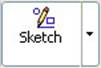 and select Circle
 . Sketch 4 circle at four edges.
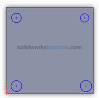
, click Normal To . Activate sketch menu by click Sketch and select Circle. Sketch 4 circle at four edges. 9. Define new circle sketch, click Smart Dimension , set diameter circle to 0.2in . Select distance for edge set to 0.3in
 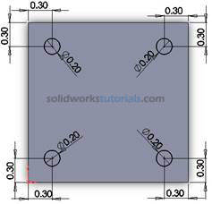 .
.
, set diameter circle to 0.2in . Select distance for edge set to 0.3in .10. Click Circle and sketch one circle at center
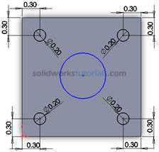 .
.
and sketch one circle at center.11. Define new circle sketch, click Smart Dimension  , set diameter circle to 1.0in . Select distance for edge set to 1.0in.
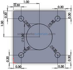
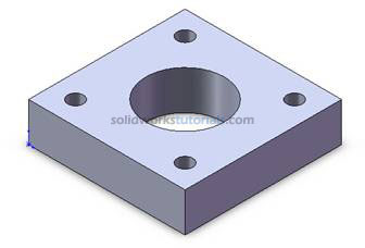
, set diameter circle to 1.0in . Select distance for edge set to 1.0in. 12. For cut click Features , click Extruded Cut
 , under Direction 1, Through All
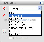 and
and  .
.
, click Extruded Cut , under Direction 1, Through All and
0 comments:
Post a Comment